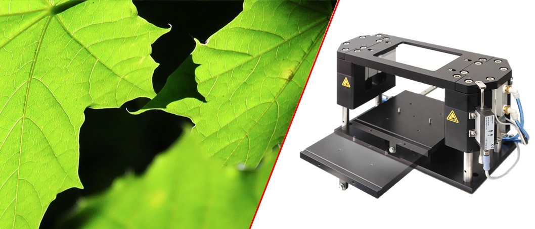
Clamping unit - pressure on parts
The clamping unit presses together the parts to be joined during the welding process. The parts are inserted into the part-specific cavity on the drawer and pressed downwards by the movement of the upper clamping plate.
The clamping force is usually provided by pneumatic cylinders, but can also be generated electrically by servo motors.
For process control, the clamping units can be equipped with displacement and force sensors as standard. The signals are read out by the Modula controller in the laser unit and can be used not only for quality analysis but also for control during the process.
Technical data and options
| Type clamping unit | small | large |
| Welding area | 150 x 100 mm | 240 x 240 mm |
| Part width maximal | 210 mm | 300 mm |
| Clamping force maximal | 2300 N | 7000 N |
- Clamping stroke: 20 mm - extendable on request
- Height of parts and cavity: extandable from 65 mm in steps of 20 mm
- Drawer movement: manual, pneumatic or electric
- Actuation clamping force: pneumatic (6 bar) or electric
- Displacement sensors: 1 or 2 with resolution 10 µm
- Force sensors: 1 or 2 with resolution 5 N
Clamping units for parts larger than described above are always individually designed and constructed.
In addition to the clamping unit, we also offer part-specific cavities and clamping tools as clamping glass or clamping frame.
Links technology
Photos clamping unit
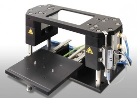
Clamping unit with drawer in outside position
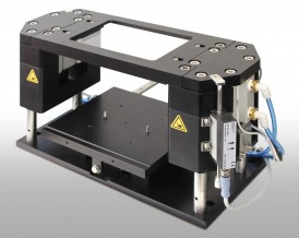
Clamping unit with drawer in inside position
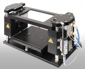 Clamping unit activated with clamping glass pressing down
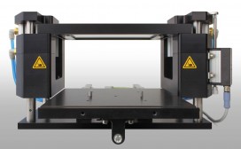
Open space of clamping unit for parts and tooling.
